Camera changer; P250
For technicians and
partly for sales managers!
This section describes the
installation, checking and adjustment procedures for the camera changer unit
and the 90º camera tube of the
“Pannoramic
This description is based on the
software version 1.15.

The described adjustments are only
done if the camera changer is new, was exchanged, disassembled or a part of it
was exchanged.
The adjustment procedures can be
used for executing checks and helping to understand the functionality of the
camera changer unit.
Contents
·
General
·
Functional overview of the camera
changer unit
·
 Dismount
and mount the camera changer unit
Dismount
and mount the camera changer unit
The camera changer unit is a component added to the Pannoramic 250 scanner. It allows using different cameras in brightfield and
fluorescent scan sessions without any image restrictions. The camera exchange
is controlled by the software at the beginning of the appropriate session.
Features
The user can
operate different cameras for the brightfield and for the fluorescent scan
sessions.
·
Without physical camera exchange
·
Without additional driver installing
·
Without additional camera adjustments
·
Without additional optical and illumination
adjustments
·
Only installed cameras can be used for scanning
Note! Do not change the
camera settings after the appropriate settings are defined in the “Microscope
Settings” dialog until the camera is not exchanged physically.
Restrictions
- It is not possible to define both cameras
for either brightfield or fluorescent scan mode at the same time.
- On the mounting for camera 1 and for camera
2 you can not mount the same camera type twice because the software
handles only cameras of different types.
- The positions for camera 1 (Fluorescent
scan mode) and camera 2 (Brightfield scan mode) are fixed on the camera
changer unit and can not be defined by the user, but any specified camera
can be mounted in any position (if it makes sense).
90º camera tube

If only 1 camera should be
used in the Pannoramic 250 (in the version brightfield scan only) a 90º
camera tube is used, instead of the camera changer unit. This camera tube
contains the same mirror as used in the camera changer unit; its position can
be also adjusted, but the motor and motor mounting does not exist.
The mirror is used in a fixed
position; the mirror disc is modified.
The image path is reflected
to the camera position 2 of the camera changer unit where the CIS-camera is
mounted.
![]() “Optical path and
Field Of View”
“Optical path and
Field Of View”
Precautions

Protect the optics of the
camera changer always against dust by the use of the appropriate dust cups or
equivalent means if the camera changer or the cameras are removed!
Attention
If the motor mounting is removed, the mirror disc
with mirror may fall out of the housing; the mirror may be damaged!
During movements, please hold
the housing so, that the tube lens shows always downward and / or secure the
mirror disc with your hand!
The
exchange of the camera changer unit is possible,
- If the stepper motor or its electronics is
faulty.
- If the shape of any part is deformed or a part is
broken.
- If the camera changer unit has any fault and you are unable to fix
it.
 Requirements
- Service program for slide scanners
(SlideScannerService.exe version 1.14 or higher) with actual license file.
- Slide scanner (version 1.14 or higher) and Slide
scanner Viewer software (SlideScanner.exe, SlideScannerViewer.exe) with
actual license files or dongles.
- 1.5, 2.5, and
- Hardware
and construction knowledge of Panoramic 250.
- Autocollimator
with camera tube adapter.
- 2
Windows tube for 60N camera adapter interface.
- The file “MicroscopeConfiguration.ini” for the
appropriate camera changer unit.
Attention: Do not mix the versions of SlideScanner.exe and SlideScannerService.exe!
Always use these programs with the same version number. Otherwise the
SlideScannerService.exe program could produce unwanted results and
SlideScanner.exe does not work correctly or even freeze!

In the file
“MicroscopeConfiguration.ini”, the camera changer unit is enabled or disabled
respectively, according to the presence of the camera changer unit or the 90º camera tube.
- The corresponding sections to the camera changer
unit are also shown.
If the 90º camera tube is present
[Version]
CurrentInifileVersion=1.9
[Microscope]
SerialNumber=xxxxx
MicroscopeType=3DMic9
ScanCameraType=
PreviewCameraType=CVrmc_m8_pPro
BarcodeReaderType=PreviewCamera
LoaderType=SL_9Mag_25Slide_Sensor_Vertical
CameraChangerType=CC_None
ReflectorTurretType=RT_None
BrightfieldLightSourceType=FlashLight2010
ObjectiveChangerType=OC_2Pos
ObjectGuideXYZType=OGXYZ_FLASH3
FlashUnitType=FlashUnit_Type2
NDFilterType=NDType2
PreviewLightType=PreviewLightUnitType_Type1
PowerSwitchBoardType=PowerSwitchBoard_Type1
Remark
If the camera changer unit type is
“CC_None” (not present), the appropriate values in the sections
[HardwareLimits] and [CameraChanger_VT] are not used; not interpreted by the
software (don’t care).
 If the camera changer unit is present
[Version]
CurrentInifileVersion=1.9
[Microscope]
SerialNumber=xxxxx
MicroscopeType=3DMic9
PreviewCameraType=CVrmc_m8_pPro
BarcodeReaderType=PreviewCamera
LoaderType=SL_9Mag_25Slide_Sensor_Vertical
CameraChangerType=CC_3DH_2Pos
ReflectorTurretType=RT_3DH_10Pos_Belt
BrightfieldLightSourceType=FlashLight2010
ObjectiveChangerType=OC_2Pos
ObjectGuideXYZType=OGXYZ_FLASH3
FlashUnitType=FlashUnit_Type2
NDFilterType=NDType2
PreviewLightType=PreviewLightUnitType_Type2
PowerSwitchBoardType=PowerSwitchBoard_Type1
[HardwareLimits]
.
.
.
CameraChangerVT_Min=-1270 ; for information only; do not use this value!
CameraChangerVT_Max=380 ; for information only; do not use this
value!
.
.
.
[CameraChanger_VT] ; at the end of the file “MicroscopeConfiguration.ini”
Position1=-1280 ; for information only; do not
use this value!
Position2=370 ; for information only; do not use this value!
Principle of camera
changing

By rotating the mirror in the
camera changer, the common brightfield and fluorescent image path, incoming
from the tube lens will be divided into a separate fluorescent image path and a
brightfield image path.
The mirror in the camera
changer reflects the image in an angle of 90 degrees to the image sensor of the
camera.
If the other camera should be
selected, the mirror rotates exactly by an angle of 180 degrees and so the
image arrives to the image sensor of the opposite camera.
The rotation of the mirror is
performed by a stepper motor.
- To reach the correct mirror plane rotation
angle, the movement of the mirror plane is stopped by adjustable, mechanical
limiters.
- To fit the mirror correctly
into the optical path, the mirror plane can be adjusted.
- The camera changer unit does not need
maintenance.
 Position of the camera changer unit
The position of the camera changer
unit is rotated by an angle of 120º against the plumb vertical; so the
edge of the brightfield camera is parallel to the edge of the magazine unit.
This adjustment can be done
only if the
tube mounting of the camera changer unit is loosened.
- Check and correct this position during the
adjustment of the
chromatic aberration.
- Mount the camera changer unit until it
stops and tighten the tube clamp.
- Loosen the camera
changer mounting bolts and rotate the camera changer unit into its
position.
- Correct the the chromatic
aberration and tighten the mounting bolts.
- Adjust the camera
rotation angle.
 Camera positions on the camera changer unit
The camera positions are 180
degrees rotated in relation to each other.
Because the mirror in the
camera changer reflects the image by 90 degrees from the camera tube to the
CMOS device or the CCD of the camera, the image will be mirrored.
If the mirror position is
changed from the camera position 2 to the camera position 1 (or vice versa),
the mirror rotates by 180 degrees and so the top and the bottom of the camera
is also rotated by 180 degrees in relation to each other.
- The shown cameras and their positions is
the standard (default) arrangement.
![]() “Usable scan
cameras” of the file “Prerequisites”
“Usable scan
cameras” of the file “Prerequisites”
 90º camera tube interfaces only the brightfield
camera
90º camera tube interfaces only the brightfield
camera
- In the dialog “Microscope
settings” of the software “SlideScanner.exe”, this camera is selected
in the “Camera position
- In the file “MicroscopeConfiguration.ini”
the option “CameraChangerType=CC_None” has to be set
- The shown camera and its position is the
standard (default) arrangement.
- The 90º camera tube does not need
maintenance.
![]() “If the 90º camera tube is present”
“If the 90º camera tube is present”

- The tube mounting
for SCAN and MIDI-type scanners (for the camera tube) is different in size
in relation to the tube mounting of the camera changer VT unit tube
(P250)!
- Check the
correct size if the turret unit was exchanged!
- Never mix the
tube mounting in the systems!

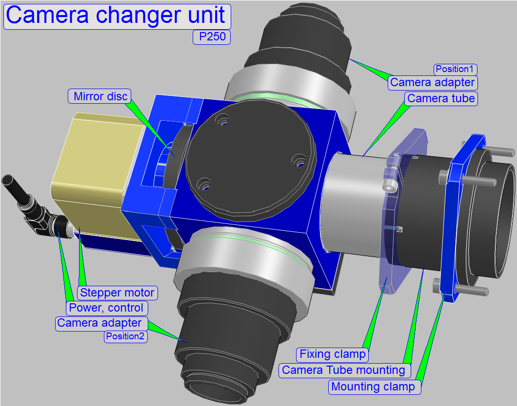
The camera changer unit
consists of:
- Housing; it contains the mountings and
drillings for the components.
- Camera tube with tube lens.
- Mountings of the 60N photo ports.
- Mirror disc with the position limiters and
the mirror mounting with mirror (removed).
- Limit position adjustment with the bumpers.
- Stepper motor mounting (removed).
- Stepper motor (removed).
The mirror can be rotated by
the help of the mirror disc in an angle of 180 degrees and so the image is
reflected to the camera adapter 1 or 2 respectively.
Attention
If the motor mounting is
removed, the mirror disc with mirror may fall out of the housing; the mirror
may be damaged!
During movements, please hold
the housing so, that the tube lens shows always downward and / or secure the
mirror disc with your hand!

One of the main components of
the camera changer is the mirror; mounted in an angle of 45 degrees into the
image path.
The mirror is surface coated,
so the image path will not be affected; the image quality is practically not
reduced.
- To clean the
mirror surface (only, if it is unavoidable!) please refer also to the chapter “Cleaning optics”.

 Mirror disc and mirror mounting
If the motor mounting is
removed, the mirror disc with mirror may fall out of the housing; the mirror
may be damaged!
During movements, please hold
the housing so, that the tube lens shows always downward and / or secure the
mirror disc with your hand!
- The mirror disc holds the mirror mounting
by 3 bolt pairs (A, B and C; see below), so the mirror plane position can
be adjusted.
- The slippage-free mounting and rotation of
the mirror disc is realized by the help of the ball bearing.
- The rotation of the mirror disc is done by
a stepper motor.

- The clutch between motor axle and mirror mounting
disc is realized with 2 compression springs; so there exist two slots (the
clutch slots), where the springs are fitting together.
- The mechanical stop position of the mirror
disc (defined by the movement limiters together with the bumpers) is equal
with the working position of the mirror for the camera position 1 and
camera position 2 respectively.
- The Home 1,2 position of the stepper motor
is inside of the possible rotation angle of the mirror disc; between the
hardware limits.
- Possible mirror positions between the
hardware limits are not defined and therefore not usable, except the
position Home1,2.
- The bumper
position adjustment is used to define the exact mirror rotation
angle of 180º between the camera positions 1 and 2.
- If the bumper position was altered, please
define the hardware
limits and the working
positions (again)!

Because the stepper motor
uses a high frequency current (more 10 kHz) in the coils to hold the actual
step position, a very little movement of the rotor can be expired.
If we would use the stepper
motor’s stop position to adjust the correct mirror position, the mirror will
vibrate in the same way as the rotor of the motor does; the seen image would be
blurry or out of focus.
To eliminate these vibrations
of the rotor, two adjustable limiter positions are created.
By the use of compression
springs in the clutch, the mirror disc will be pressed against the appropriate
limiter and so, vibrations will not take effect and are eliminated.
- Check the movement of the mirror disc
manually, it should move easily and smoothly between the limit positions.

The guaranteed movement range
of the unit is exactly 180º (= ½ revolution) of the mirror plane,
but the rotor does more than 1600steps (= ½ revolution) because the
springs in the clutch are pressing the limiters against the bumpers.
Because the position of the
clutch pins on the motor axle is not defined in the center of the guaranteed
movement range (between the adjustable bumper positions), the position Home1,2
may meet the guaranteed movement range more 100steps away from the center; this
is shown as “Variable position”. In other words, the position Home1,2 is only
in exceptions in the center of the movement range.
 Because the
position of the “Pin connection” is not defined on the motor axle if the motor
stays in Home1,2, a so called “Variable position” exists.
Because the
position of the “Pin connection” is not defined on the motor axle if the motor
stays in Home1,2, a so called “Variable position” exists.
·
The position of the pin connection in relation to the
motor axle’s Home1,2 position may be anywhere in the guaranteed movement range
of the mirror disc, but the limit Home1 must not be reached!
![]() “How to define hardware limits” and “Limiter position
range”
“How to define hardware limits” and “Limiter position
range”

The positions “C” must not exceed
the limit “Home1”.

![]() “How to define the hardware limits”
“How to define the hardware limits”

 The stepper motor
electronics gets its commands via the cable STJ-5.
The stepper motor
electronics gets its commands via the cable STJ-5.
The address of the stepper
motor electronics is 10.
If the motor found the
position Home1,2, anywhere between the two limit positions (during start up),
the motor will be rotated to the camera position 2. Thereafter the software
rotates the mirror always by -180° or +180° respectively by using the step
number for the given camera position.
- In the file “MicroscopeConfiguration.ini”,
section [CameraChanger_VT] the values for the camera changer working
positions are defined. The working position for the mirror in the camera
position 1 and 2 are shown in motor steps (these values are different for
each camera changer unit!!).
Attention
If the motor mounting is
removed, the mirror disc with mirror may fall out of the housing; the mirror
may be damaged!
During movements, please hold
the housing so, that the tube lens shows always downward and/or secure the
mirror disc with your hand!

 The clutch is
realized with 2 clutch slots in the mirror disc and two pins on the clutch part of the motor.
The clutch is
realized with 2 clutch slots in the mirror disc and two pins on the clutch part of the motor.
The motor is rotated about 10
… 20 steps more as required for the mirror working position. With this solution,
the compression springs in the clutch part of the mirror disc are pressed; the
limiters of the mirror mounting disc are pressed onto the appropriate bumper
(the mechanical stop position) and any slip or vibration of the mirror is
eliminated. Please take this into account, if you are doing the adjustments.
The compression spring presses the ball bearing of the mirror disc into
the housing and so the mounting will be slippage-free.
- If the Motor mounting is removed, the technician
has to fulfill the tasks of the motor with its mounting manually during
the mirror plane adjustment checks, it means:
- During checks, press the mirror disc
always into the housing (as it would do the compression spring) and
- During checks, rotate the mirror disc
always against the bumpers (as it would do the stepper motor).
The clutch

- Before assembling, set the stepper motor to
the position Home1,2 with the service program.
- Fit the
spring onto the clutch part on the motor side.
- Fit the
clutch pins into the slots of the clutch part in the mirror disc
(between the two springs); a little pressure will be required.
- To fit the pins correctly, rotate always only the mirror
disc, never the stepper motor’s rotor!
- If the connection fits correctly, keep the
motor mounting under pressure against the mirror disc and drive in the
motor mounting bolts.
90º camera tube
This part is a simplified
version of the camera changer unit; it allows a more cost-effective solution if
only 1 camera should be connected.
 In practice, the mirror is
mounted in a fixed position; the stepper motor with clutch is left out.
In practice, the mirror is
mounted in a fixed position; the stepper motor with clutch is left out.
This solution is used in the
Pannoramic 250 BF (brightfield scan only).
- In the file “MicroscopeConfiguration.ini”
the option “CameraChangerType=CC_None” has to be set
![]() “If the 90º camera tube is present”
“If the 90º camera tube is present”
Differences
between P250BF and P250FL.

 The modified mirror disc is
mounted in a fixed position by 3 bolts; it can be rotated in a small range,
some tenth mm, only.
The modified mirror disc is
mounted in a fixed position by 3 bolts; it can be rotated in a small range,
some tenth mm, only.
- The mirror mounting is connected to the
mirror disc by the use of three bolt pairs; so the mirror
plane position can be adjusted.

In the center of each window
of the 2 windows tube a drilling can be found; this is the marker position for
the adjustment.
The window 1 is used to find the
position of the mirror plane by shifting the mirror on the optical axis.
The marker in the window 2 is
used to determine the inclination angle of the mirror against the optical axis.
If the LASER-beam of the
autocollimator crosses the markers of both windows, the adjustment is correct.
- To align the mirror position we recommend
the use of two tubes, mounted onto the photo port in the camera position 1
and 2 at the same time.
- Mount the 2 windows tube until it stops and
so, that the window 1 is near to the mirror.

The autocollimator adapter is
used to mount the autocollimator onto the tube part.
- The correct, centermost mounting of the autocollimator
to the adapter as well as the correct calibration of the autocollimator is
essentially important for a successful adjustment result!
- If there a backlash or gap exist between
the autocollimator mounting and the adapter, please eliminate it first,
before tightening the mounting bolts of the adapter!

An autocollimator
is an optical instrument for non-contact measurement
of angles.
They are typically used to align components and measure deflections
in optical or mechanical systems. An autocollimator works by projecting an
image onto a target mirror,
and measuring the deflection of the returned image against a display with a scale,
either visually or by means of an electronics detector. A visual autocollimator
can measure angles as small as 0.5 arc seconds.
The scale of the
autocollimator can also be used to qualify the adjustment. If the reflected
beam is near to the center (or in the center of the display; then the beam is
not displayed on the scale) and both marker positions in both 2 windows tubes
are crossed, the adjustment can be assumed as finished.
Attention
·
 To avoid harm of your eye, please do not look directly into the beam of
the autocollimator!
To avoid harm of your eye, please do not look directly into the beam of
the autocollimator!
- Mount the autocollimator adapter together
with the autocollimator onto the thread on the tube lens side until it
stops.
- Very important for the following
adjustments is the correct mounting between autocollimator and adapter as
well as the calibration of the autocollimator, because any deviation of
the beam from the center implies a misalignment of the mirror after
adjustments!

How
to check the autocollimator’s calibration
- Clamp or fix the adapter with loosened
fixing bolts in a parallel vise so, that the autocollimator may be rotated
in the adapter.
- Eliminate or reduce the possible gap
between autocollimator and adapter by using adequate tools like fitting
tubes, fitting plates or fitting rings; the autocollimator should be even
rotate-able; and switch it on.
- Affix the screen onto the
wall in a distance of about 0.5m, use the LASER beam.
- Rotate the Autocollimator and check the
behavior on the
screen.
- If the deviation from the center is too much
(outside of the green area), the LASER beam of the autocollimator have to
be centered and calibrated.
The calibration of the
autocollimator makes the LASER beam centermost in relation to the mounting of
the autocollimator.
To reach this, the LASER
diode is often situated in a tube and the end of the tube can be positioned by
3 bolts; these are arranged in an angle of 120° to each other.
By driving 1 bolt outward and
the other two bolts inward or vice versa, the position of the tube end will be
modified and so the LASER beam can be centered. After each modification of the
adjustment bolts check the result as
described above.
Adjustment tools mounted


Mount the components for
checks and the adjustment as shown.
Drive each mounting until it stops!
All here described stepper
motor movements are done with the tab “CameraChangerVT” of the service
program. The accuracy of the stepper motor limits is 10 steps.
- In this chapter only adjustment techniques
are described as “stand alone procedure”, without any sequence, necessary
for the adjustment.
- By combining the techniques in a proper
sequence, the real adjustment sequence can be found; an example is shown
in the chapter “Adjust
the camera changer unit”.
- Take into account, that the alignment of
the mirror plane (shift, inclining and rotation) is a complex adjustment,
it means, this techniques can not be used independently from each other;
e.g. if the inclination of the mirror plane was modified may be the shift
position and the rotation position of the mirror plane has to be corrected
also; it is an iteration process!

Check the hardware limits by
using the values of the file “MicroscopeConfiguration.ini”, section [HardwareLimits] for this, actual camera
changer unit.
1)
In the service program set the value of the parameter
“CameraChangerVT_Min=” and move the stepper motor to
this limit.
2)
Press Home1 only; there should not be steps lost.
3)
If there are steps lost, define the appropriate limit
again; see “Find the hardware
limits”.
4)
Set the value of the parameter “CameraChangerVT_Max=” and move the stepper motor
to this limit.
5)
Press Home1 only; there should not be steps lost.
6)
If there are steps lost, define the appropriate limit
again; see “Find the hardware
limits”.
·
Find the working positions in the file
“MicroscopeConfiguration.ini”, section [CameraChanger_VT] for this, actual
camera changer unit.
7)
Set the value for the camera position 1 and move the
stepper motor with the service program to this position; a click should be
listened.
8)
Press Home1 only; there should not be lost steps.
9)
Set the value for the camera position 2 and move the
stepper motor to this position; a click should be listened.
10)
Press Home1 only; there should not be lost steps.
11)
If there are steps lost or a click sound is not
audible, define the hardware
limits and the values for the camera position 1
and 2 again; check also the movement of the mirror disc, it should move
easily and smoothly between the limit positions.
To define the
hardware limits the bumper positions have to be adjusted correctly, all the
optical adjustments have to be finished and the camera changer unit has to be
fully assembled.
![]() “How to define the hardware limits”
“How to define the hardware limits”
Find the positive
limit
1)
With the service program, in the tab
“CameraChanger_VT” Press Home1,2 and then go with the step button “100 steps”
forward (in positive direction), until a click sound is audible; memorize this
step number.
2)
Type in the found number of steps in the field “Step”
of the tab “CameraChanger_VT”
3)
Press Home1,2.
4)
 Go forward (in
positive direction) the (new) step size number and then backward again.
Go forward (in
positive direction) the (new) step size number and then backward again.
5)
Press Home1 only.
6)
If there are no steps lost, increase the number of
steps in the field “Step” by 10.
7)
Repeat from step 3 until no steps are lost.
8)
If there are steps lost the first time (more then 2
steps) then the position (D) of the
example on the right is found.
9)
Decrease the number of steps in the field “Step” by
10.
10)
Press Home1,2.
11)
Go forward the new step size number and then backward
again.
12)
Press home 1 only.
13)
If there are no steps lost (not more then 2 steps)
then the position (C) of the example
on the right is found; memorize this number.
14)
Type in the memorized step number for the audible
click sound, check and define this step number more precise, then the position (A) of the example on the right is
found.
15)
Calculate the number of steps, used as hardware limit
with the formula B=A + ((C - A) / 2); now the
value (B) is found.
16)
Update the
value of the parameter “CameraChangerVT_Max=” in the section
[HardwareLimits] of the file “MicroscopeConfiguration.ini” with the value of (B) and save
the file.
 Find the negative limit
17)
In the tab “CameraChanger_VT” press Home1,2 and then
go with the step button “-100 steps” backward (in negative direction), until a
click sound is audible; memorize this step number.
18)
Type in the found number of steps in the field “Step”
of the tab “CameraChanger_VT”
19)
Press Home1,2.
20)
Go backward (in negative direction), the (new) step
size number and then forward again.
21)
Press Home1 only.
22)
If there are no steps lost, increase the number of
steps in the field “Step” by 10.
23)
Repeat from step 19 until no steps are lost.
24)
If there are steps lost the first time (more then 2
steps) then the position (D) of the
example on the right is found.
25)
Decrease the number of steps in the field “Step” by
10.
26)
Press Home1,2.
27)
Go backward (in negative direction), the new step size
number and then forward again.
28)
Press home 1 only.
29)
If there are no steps lost (not more then 2 steps)
then the position (C) of the example
on the right is found; memorize this number.
30)
Type in the memorized step number for the audible
click sound, check and define this step number more precise, then the position (A) of the example on the right is
found.
31)
Calculate the number of steps, used as hardware limit
with the formula B=A + ((C - A) / 2); now the
value (B) is found.
32)
Update the
value of the parameter “CameraChangerVT_Min=” in the section
[HardwareLimits] of the file “MicroscopeConfiguration.ini” with the value of (B) and save
the file.
The hardware limits are
correct, if:
- The sum of the absolute number of steps for
the upper and lower limit is more then 1600 steps (a half revolution of
the rotor = 1600 steps; and this is equivalent to 180° of the mirror
rotation).
- If a click sound is audible during reaching
the positive and the negative limit.
- No steps are lost in the limit position
(checked with the service program).
Define the mirror
disc working position
The mirror disc (and so the
camera) working positions are easily defined by reducing the found, absolute
values for the hardware limits by 10 steps.
Example
If the Hardware limits are found as
shown:
[HardwareLimits]
CameraChangerVT_Min=-1270 ; for information only; do not use this value!
CameraChangerVT_Max=380 ; for information only; do not use this
value!
The working positions for the
cameras will be:
[CameraChanger_VT] ; at the end of the file “MicroscopeConfiguration.ini”
Position1=-1260 ; for information
only; do not use this value!
Position2=370 ; for information only; do not use
this value!
Mirror plane
position adjustment
The proper result of the
following adjustments depends highly on the calibration of the autocollimator
and the correctness of the mounting between autocollimator and adapter. If
there is a deviation from the center, the result includes this deviation also;
see above, “The autocollimator”!
The mirror plane position
alignment can be divided into 3 main actions:
·
Shifting,
·
Inclining and
·
Rotation of the mirror plane.
These actions are described
separately, but during the adjustment, these actions are combined as necessary
to reach the proper mirror position; always the momentarily check decides, what
to do next.
- We assume the adjustment tools
are mounted properly.
How to check the rotation angle
- Rotate the mirror disc some mm away from
the bumper and against the bumper more times manually.
- Decide by the help of the beam movement,
whether the bumper position modification would eliminate the deviation or
not.
- If required, adjust the appropriate bumper
position.
How to check the shift position
- Check the beam position in the window 1 of
both camera positions.
- If the Motor mounting is not removed, press
the mirror disc against the bumper manually, during the check.
- If the Motor mounting is removed, the
technician has to fulfill the tasks of the motor with its mounting
manually, it means:
- During checks, press the mirror disc
always into the housing (as it would do the compression
spring on the motor side) and
- During checks, rotate the mirror disc
always against the bumpers (as it would do the stepper motor).
How to check the inclination angle
- Check the beam position in relation to the
markers of the window 1 and window 2 as well as the display of the
autocollimator. Check the result in the opposite camera position also.
- If required, modify the mirror position by
shifting and / or inclining.
- If the Motor mounting is not removed, press
the mirror disc against the bumper manually, during the check.
- If the Motor mounting is removed, the
technician has to fulfill the tasks of the motor with its mounting
manually, it means:
- During checks, press the mirror disc
always into the housing (as it would do the compression
spring on the motor side) and
- During checks, rotate the mirror disc
always against the bumpers (as it would do the stepper motor).
Mirror plane position
adjustment
 The proper result
of the following adjustments depends highly on the calibration of the
autocollimator and the correctness of the mounting between autocollimator and
adapter. If there is a deviation from the center, the result includes this
deviation also; see above, “The
autocollimator”!
The proper result
of the following adjustments depends highly on the calibration of the
autocollimator and the correctness of the mounting between autocollimator and
adapter. If there is a deviation from the center, the result includes this
deviation also; see above, “The
autocollimator”!
The mirror plane position
alignment can be divided into 3 main actions:
·
Shifting,
·
Inclining and
·
Rotation of the mirror plane.
These actions are described
separately, but during the adjustment, these actions are combined as necessary
to reach the proper mirror position; always the momentarily check decides, what
to do next.
- We assume the adjustment tools
are mounted properly.
 How to check the rotation
angle
How to check the rotation
angle
- Switch the autocollimator on and check the
position of the laser beam in the window 1.
- If an inacceptable deviation will be
detected, (3 or 4), loosen the mirror disc mounting bolts.
- Decide by the help of the beam movement,
whether the rotation angle adjustment would eliminate the deviation or
not.
How to check the shift
position
- Check the beam position in the window 1.
- If the shift position of the mirror plane
is incorrect (1 or 2) the mirror plane has to be shifted toward (2) the
autocollimator or away (1) from it;
How to check the
inclination angle

- Check the beam position in relation to the
marker of the window 2 as well as the marker position in the window1.
- If the beam meets the center in the window
1 and there is an inacceptable deviation from the center in window2, the
inclination of the mirror plane is incorrect.
- Incline and shift the mirror plane as
required;

- By driving the bolts of the pairs A, B and
C in or out, the mirror plane position will be modified.
- The bolts without heads define the mirror
plane position (named as “plane position bolts”) and the bolts with heads
(named as “fixing bolts”) fixing the adjusted position.
- With this solution the shift and
inclination of the mirror plane becomes possible.
- By loosening the fixing bolts and
tightening the plane position bolts (or vice versa), the mirror plane will
be modified.
- If the
quantity of the screw driver rotation is equal on all the three bolt pairs A, B and C,
the mirror plane will be shifted on the optical axis; it means, if we are
using on all three bolt pairs a full revolution (360 degrees) or a half
revolution of the screw driver, the
mirror surface will be shifted on the optical axis.
- In opposite to this, if the rotation angle of the screw driver is not equal on all three bolt pairs, the mirror plane will be inclined.
- By combining shifting and inclining, the
mirror plane can be aligned exactly into an angle of 45º.
- The incorrect adjusted mirror plane affects
the image quality and the image size!
Shift the mirror plane on the optical axis


- Loosen all the plane position bolts and
tighten the fixing bolts; in this way, a defined start position for the
adjustment is found; see position (a).
- The plane position bolts should be fully
loosened and the fixing bolts should be fully tightened.
- Check the mirrored beam in the lower window
of the two windows tube.
- If the beam do not met the hole in the
center of the window 1, shift the mirror plane until the center is
reached; see position (b).
- Loosen the 3 fixing
bolts by about a ½ revolution and then tighten the plane position
bolts. Hereby not the ½ turn is important; instead the turn
quantity should be nearly equal on all the three plane position bolts.
This way the mirror surface will be shifted on the optical axis until the
center is reached.
- Check the alignment
in the lower window of both camera positions.


- If the beam crosses the center of the
window 1, check the beam position in relation to the window 2.
- If the center in the window 2 is not met, modify
the inclination angle by driving the bolt pair (A) or the bolt pairs (B)
and (C); this way, the inclination angle up or down of the mirror plane
will be affected.
- By modifying the position of the bolt pairs
(B) or (C), the inclination angle left or right will be affected.
- After each drive of any bolt pair check the
beam position in both windows!
- Take into account that the correct
adjustment is shown in the windows 1 and 2 only, if all fixing bolts are tightened.
- Check the adjustment
in both camera positions.
- If the Motor mounting is removed, the
technician has to fulfill the tasks of the motor with its mounting
manually, it means:
- During checks, press the mirror disc
always into the housing (as it would do the compression
spring on the motor side) and
- During checks, rotate the mirror disc always
against the bumpers (as it would do the stepper motor).
- If the adjustment is
finished and the unit is fully assembled again, check or define the hardware limits and the
working
positions (again), before the start of the scan program!

- By loosening the mirror disc mounting bolts
of the “90º camera tube” the
mirror can be rotated left or right in a very small range only, but it may
help to find the correct mirror position.
 By adjusting
the bumper position (2), the correct rotation angle of the mirror disc can
be found.
By adjusting
the bumper position (2), the correct rotation angle of the mirror disc can
be found.
- If the bumper position was altered, define
the hardware limits
and the working
positions (again), before the start of the scan program!
As discussed previously, the
bumper position is used to define the rotation angle of the mirror disc in an angle
of exact 180 degrees.
 Before the motor
with its mounting will be removed, the bumper position should be checked and /
or adjusted.
Before the motor
with its mounting will be removed, the bumper position should be checked and /
or adjusted.
1)
Disconnect the motor cable.
2)
Remove
the camera changer unit.
3)
Mount
the adjustment tools.
4)
Rotate the mirror disc by hand a little bit away from
the bumper and toward the bumper again, more times and observe the movement of
the LASER beam.
5)
Decide, whether the bumper position adjustment would
correct the mirror plane or not.
6)
If the bumper position seems to be correct, repeat the
procedure, described from step 4 with the opposite bumper position.
Adjust the bumper position
7)
Loosen the counter nut of the appropriate bumper
adjustment bolt and drive the bolt outward a little bit.
8)
Press the mirror disc against the bumper by hand and
drive in the adjustment bolt until the marker position in both windows are met.
9)
Hold the adjustment bolt in its position and tighten
the counter nut.
10)
Check
the bumper position from step 4.
11)
Check
the LASER beam in relation to the markers in the opposite bumper position also.
- If the bumper position adjustment does not
deliver the desired result, remove the motor
with mounting and adjust the mirror plane position more precise; use the
procedures as described under “Shift the mirror plane
on the optical axis” and “Incline the mirror
plane”; see also “If the
mirror plane needs adjustment”
- If the Motor mounting is removed, the technician
has to fulfill the tasks of the motor with its mounting manually, it
means:
- Press the mirror disc always into the
housing during the checks (as it would do the compression
spring on the motor side) and
- Rotate the mirror disc always against the
bumpers (as it would do the stepper motor).
- If the entire adjustment is finished,
define the hardware
limits and the working
positions (again).
 This operation
should be done only, if the plane position of the mirror must be aligned or the
mirror should be cleaned. This procedure is usually not done in the field and
assumes that the previous adjustment “Check or adjust the bumper position” is
finished and correct.
This operation
should be done only, if the plane position of the mirror must be aligned or the
mirror should be cleaned. This procedure is usually not done in the field and
assumes that the previous adjustment “Check or adjust the bumper position” is
finished and correct.
1.
Set the motor to the position Home1,2. Thereafter do
not rotate the motor axle until the clutch housing is assembled again.
2.
Disconnect the cable STJ-5.
3.
Remove the 4 mounting bolts.
4.
If all 4 mounting bolts are removed, pull the motor carefully away from the mirror disc.
5.
To clean the mirror, you can also pull out the mirror
mounting disc carefully.
Attention
If the motor mounting is
removed, the mirror disc with mirror may fall out of the housing; the mirror
may be damaged!
During movements, please hold
the housing so, that the tube lens shows always downward and / or secure the
mirror disc with your hand!
Mount the motor and clutch housing

6.
Make sure the spring is on the part of the clutch on
the motor side.
7.
During assembling the clutch fit the pins into the slots
between the two springs; a little pressure is required. If necessary, rotate
the mirror mounting disc, never the
motor axle!
8.
Hold the motor mounting under pressure against the
mirror disc, mount the clutch housing with the mounting bolts and tighten them.
9.
Connect the cable STJ-5.
10.
Check the clutch connection by checking the hardware
limits, see the adjustment procedure above. The connection is correct, if the
hardware limits has not changed (if the bumper positions was not altered).
Adjust the camera changer unit
All procedures and
adjustments described below should not be executed in the field, because any
manipulation on the mirror position and mirror plane mounting needs a full
adjustment of the mirror and the needed adjustment tools are mostly not
available in the field.
The shown sequence can
differ, according to the task to be done; the used techniques are described
above in the chapter “Adjustment
techniques” and can be combined as necessary.
- Check the mirror plane position in both
camera positions.
- If adjustments are required, check the
correctness of the
bumper positions first.
- If the mirror plane is further incorrect,
adjust the correct mirror position by shifting, inclining and rotation of the
mirror plane.
- Assemble the
motor with mounting and check the working positions manually also.
- If the adjustment is finished, define the hardware limits and the
working
positions (again).
- Before dismounting the adjustment tools,
check the working positions and the entire adjustment with the service
program and the LASER beam.
- Mount
the camera changer unit.
How to check the camera changer unit?
 Before we are
starting to adjust the camera changer unit, and also, if we have finished the
adjustment (and the unit is already assembled again), the actual mirror
positions and the adjustments should be checked.
Before we are
starting to adjust the camera changer unit, and also, if we have finished the
adjustment (and the unit is already assembled again), the actual mirror
positions and the adjustments should be checked.
- Mount the adjustment tools
- In the file “MicroscopeConfiguration.ini”
find the corresponding values for the camera changer working positions in
the section [CameraChanger_VT]. The working position for the mirror in the
camera position 1 and 2 are shown in motor steps (these values are
different for each camera changer unit!!).
- With the service program move the motor to
Home1,2 and then to the appropriate mirror position.
- If the mirror position is reached, a click
(sound) should be listened.
- Press Home1 only; there
should not be lost steps.
- Check this behavior in both camera
positions.
- Move the mirror to its working position
again.
- Check the LASER beam in relation to the
window 1 and 2 and on the display of the autocollimator also.
- Check the same parameters in the opposite
mirror position.
- Decide, whether the mirror needs adjustment
or not.
![]() “How to define the hardware limits”
“How to define the hardware limits”


Procedure of a full adjustment
Remove the camera changer unit
from the scanner P250.
1)
Mount
the adjustment tools.
2)
 With the service
program set active the tab “CameraChanger_VT” and set the stepper motor to
Home1,2.
With the service
program set active the tab “CameraChanger_VT” and set the stepper motor to
Home1,2.
Check the hardware
limits
3)
Check
the hardware limits by using the values of the file
“MicroscopeConfiguration.ini”, section [HardwareLimits] for this, actual camera changer unit.
4)
If there are steps lost, adjust the appropriate limit
again.
5)
Find the working positions in the file “MicroscopeConfiguration.ini”,
section [CameraChanger_VT] for this, actual camera changer unit.
6)
Set the value for the camera position 1 and move the
stepper motor with the service program to this position; a click should be
listened.
7)
If there are steps lost, define the
working positions and the values for the camera position 1
and 2 again; check also the movement of the mirror disc, it should move
easily and smoothly between the limit positions.
Check the mirror
plane position
8)
With the service program, set the value for the camera
position 1 and move the stepper motor to this position.
9)
Check the LASER beam in relation to the marker
positions in the windows 1 and 2 of the 2 windows tube and check the reflected
beam on the scale of the autocollimator also.
10)
Set the value for the camera position 2 and move the
stepper motor to this position.
11)
Check the LASER beam in relation to the marker
positions in the windows 1 and 2 of the 2 windows tube and check the reflected
beam on the scale of the autocollimator also.
12)
Repeat the previous 4 steps as necessary and decide,
whether the camera changer unit needs adjustment or not.
If the mirror plane needs
adjustment
First check the
limit positions (the bumper
position) on the appropriate camera position.
13)
 If further mirror
plane position adjustments are required, set the stepper motor to Home1,2 and remove the motor
mounting.
If further mirror
plane position adjustments are required, set the stepper motor to Home1,2 and remove the motor
mounting.
14)
Rotate the mirror disc manually into the appropriate
camera position and execute the appropriate procedures as described in the
chapter “The
mirror plane position adjustment”.
15)
Check the adjustment in both working positions in the
windows 1 and 2 of both 2 windows tubes and always on the scale of the
autocollimator also.
16)
If the adjustment is finished, mount the motor adapter.
17)
Execute the checks logically as described in the
chapter “How to
check the camera changer unit”; rotate the mirror disc
manually.
18)
Check or define the hardware limits
and the
working positions of the camera.
19)
Execute the checks logically as described in the
chapter “How to
check the camera changer unit” with the found limits and the service
program.
20)
Mount
the camera changer unit.
21)
 Update the
parameter values in the sections [HardwareLimits] and
[CameraChanger_VT] of the file
“MicroscopeConfiguration.ini”.
Update the
parameter values in the sections [HardwareLimits] and
[CameraChanger_VT] of the file
“MicroscopeConfiguration.ini”.
22)
Save the files “MicroscopeConfiguration.ini” and
“MicroscopeSettings.ini” into the EEPROM.
23)
Scan one or more tissues and check the adjustment
result.
Dismount and mount the camera changer unit
The entire camera changer
unit is mounted to the turret unit via the tube mounting and the tube mounting
clamp.

Remove the camera changer unit
1.
Remove the camera adapters with the cameras from the
camera changer unit.
2.
Disconnect the cable STJ-5.
3.
Loosen the tube fixing clamp.
4.
Unscrew the camera tube with the entire camera changer
from the tube mounting.
5.
Remove the tube fixing clamp from the tube.
Mount the camera changer unit
6.
Fit the tube fixing clamp onto the tube mounting.
7.
Drive the camera tube part into the tube mounting until
it stops.
8.
Tighten the tube fixing clamp; see also “Position of the
camera changer unit”.
9.
Mount the camera adapters with the cameras.
10.
Connect the cable STJ-5.
11.
Start the program SlideScanner.exe and adjust the camera rotation
angle for each camera.