Focus unit; PCON
For technicians and
partly for sales managers!
These instructions describe the
procedures to install and adjust the focus unit of the scanner Pannoramic
Confocal. To help resolve problems with the focus unit a hardware description of
implemented components and adjustment procedures are added.
· Software relevant settings are based on the software
version 1.19.

Contents
- General
- Functional
overview of the focus unit
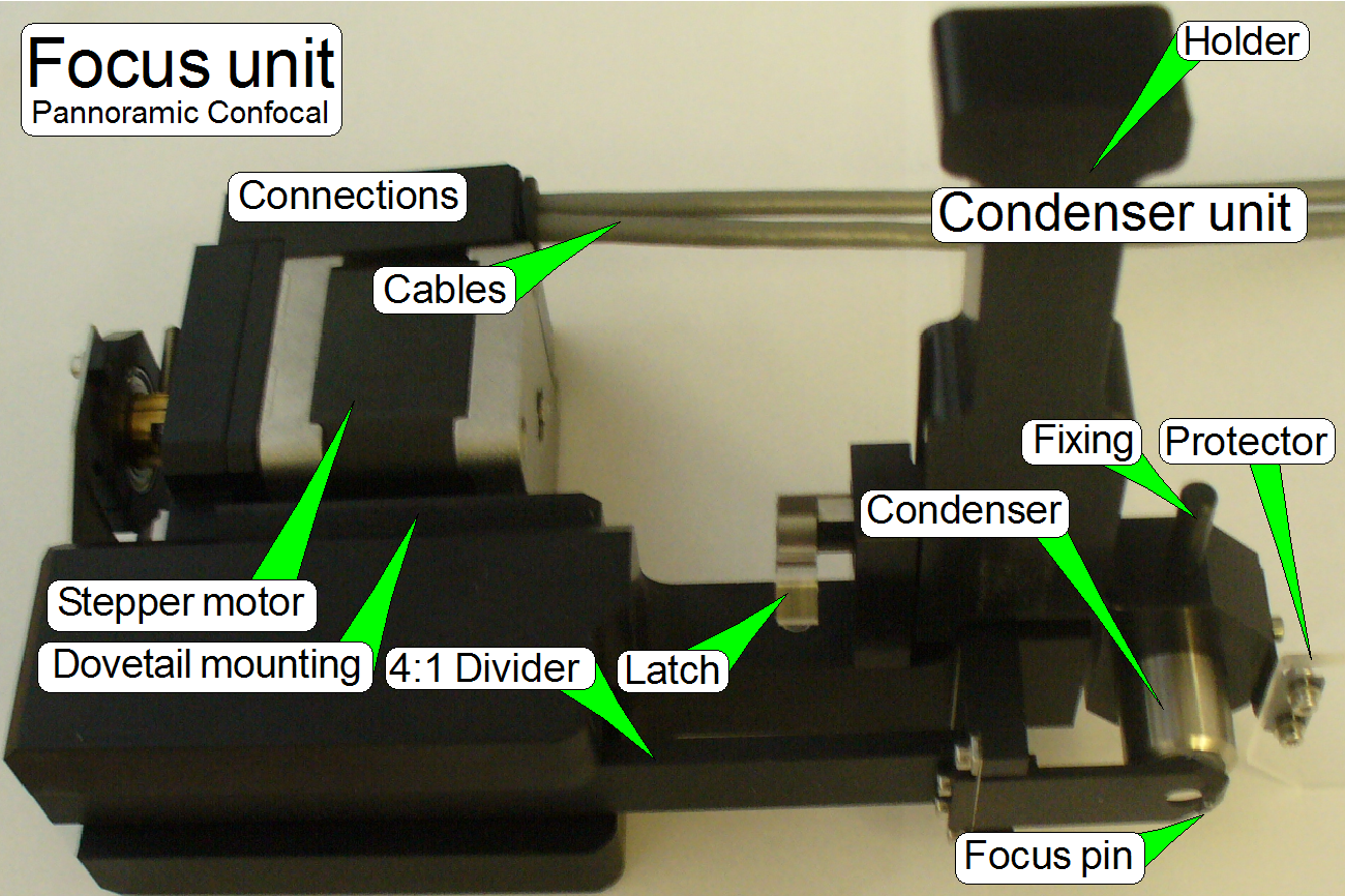
- Components and construction
 The described
focus unit is a component of the scanner Pannoramic Confocal and includes the following
main parts:
The described
focus unit is a component of the scanner Pannoramic Confocal and includes the following
main parts:
The focus unit is derived
from the P250 and contains the following modifications:
·
Objective changer is separated from the focus unit; it
is mounted separately, keeps a separate unit and description
·
To clean the condenser unit, it is constructed
removable, contains an acryl glass protector and is fixed with a latch.
·
Adjustment of the optical axis is modified and might
require checks after adjustments.
·
Shutter mechanics is separated and situated on the
scanner plate; so the shutter arms are not required. In analogy to the other
scanners, it will be discussed here.
·
Because the shutter arms are removed, the focus unit
does not use hardware limits! To see and check the ex-center position, only a
visualization pin is used.
Remark
Might be, there are inherit
images and texts from the P250. To make all the helpful images needs time!
Please be insightfully, I’m working on it!
The
focus unit gives the possibility of
focusing the FOV (field of view,
seen by the scan camera) automatically during the scan process of the sample.
The objective changer unit is separately mounted (not
onto the focus unit) and allows the consecutive use of two, preinstalled
objectives. The selection or exchange of the objective is initiated by software
before a slide scan session is started. The movement of the objective holder
disc is executed via a DC-motor and the position is sensed via Hall sensors.
Each objective position has a separate hall sensor, so the software knows
always which objective is actually in use. To guarantees the proper position of
the objective in the light path, the final objective position is fixed via a
form-fit mechanism.
The unit was developed for
the use of objectives of the following types:
Plan-APOCHROMAT
20x/0.8 and C-APOCHROMAT
40x/1.2W
The objective type
“Apochromat” contains several, special chromatic and spherical corrections and
delivers so an image of very high color trueness with very small spherical
aberration.
If the mechanical dimensions
do not exceed the size of the Plan-APOCHROMAT 40x0.95 type objective, the
mechanical mounting is identical and the focus distance of the objective to the
tissue is not closer then 0.25mm, other kind of objectives can be used also but
it is strongly not recommended! Always check with 3DHISTECH first if a
different objective should be used!
The shutter mechanics covers the
condenser and this way the bright field illumination path is broken during
fluoresce scan sessions. The two commands, “condenser cover off” and “condenser
cover on” are defined by a number of steps, executed by the shutter motor.
Automatic scan
In the slide scan table of
the scan program “SlideScanner.exe” you may assign the objective with which the
slide should be scanned. In other words, the objective can be changed any time
between two slide scanning procedures. If the slide scan table does not contain
information about the objective, the scan procedure will be done with the
actual objective.
Manual scan
 The objective can be changed any time, before
the scan procedure is started.
The objective can be changed any time, before
the scan procedure is started.
The exchange of the focus unit is possible:
- If the stepper motor or its connection is faulty
- If the shape of any part is deformed or a part is
broken.
- If the focus unit has any fault and you are unable to
fix it.
Requirements
- Service program for slide scanners (SlideScannerService.exe) with
actual license file
- Slide scanner (version 1.19 or higher) and Slide
scanner Viewer software (SlideScanner.exe, MViewer.exe) with actual
license files or dongle
- 1.5, 2.5, 3 and
- Hardware
and construction knowledge of the scanner Panoramic Confocal
 Attention: Do not mix the versions of SlideScanner.exe and
SlideScannerService.exe! Always use these programs with the same version number.
Otherwise the SlideScannerService.exe program could produce unwanted results
and SlideScanner.exe does not work correctly or even freeze!
Attention: Do not mix the versions of SlideScanner.exe and
SlideScannerService.exe! Always use these programs with the same version number.
Otherwise the SlideScannerService.exe program could produce unwanted results
and SlideScanner.exe does not work correctly or even freeze!
Since the software version 1.15 the units of the scanner are configured
in the file “MicroscopeConfiguration.ini”, section [Microscope].
· The
path of the file MicroscopeConfiguration.ini, in the software version with the
operating system Windows® 7 is:
C:\ProgramData\3DHISTECH\SlideScanner\MicroscopeConfiguration.ini
 [Microscope]
SerialNumber=PCON_xxx
MicroscopeType=3DMic10
MicroscopeSubtype=Confocal
ScanCameraType=
PreviewCameraType=CVrmc_m8_pPro
BarcodeReaderType=PreviewCamera
LoaderType=SL_1Mag_12Slide_Sensor_Horizontal2
CameraChangerType=CC_none
ReflectorTurretType=RT_None
BrightfieldLightSourceType=RGBLedLight
ObjectiveChangerType=OC_2Pos
ObjectGuideXYZType=OGXYZ_FLASH4
FlashUnitType=NoFlashUnit
NDFilterType=NDType_None
PreviewLightType=PreviewLightUnitType_Type2
ShutterMotorType=Shutter_Motor
PowerSwitchBoardType=PowerSwitchBoard_Type1
ConfocalUnitType=ConfocalUnitType_Aurox
WaterFeederType=WaterFeeder_Type1
Functional overview of the focus unit
Physically, the focus
position is defined by the distance of the objective to the tissue. If the
tissue is in the focus of the objective, a sharp image is seen by the camera.
Because the tissues are different from each other in thickness, and the
thickness can change inside the same tissue also, the focus position must be
checked and corrected always, during the scan procedure.
- In Pannoramic scanners, as well as in the
PCON, the real focus position is found by moving the slide toward or away
from the objective via the focus pin.
- The focus position is influenced by both,
the fixed (adjustable) objective position and the actual position of the
focus pin.
Furthermore, if the slide as
well as the objective will be changed, the specimen holder must be moved away
from the objective to avoid collision.
If the shutter is changed
from shutter off to shutter on or vice versa, the specimen holder is moved to a
position where the focus pin is not in connection with the slide or the
specimen holder. This way, the distance between specimen holder (cover slip)
and objective is not affected if the ex-center crosses the upper peak of the
sine wave.
During all these actions,
except focusing, the objective must be protected against touching the cover
slip and the focus pin and 4:1 divider must be protected against overstraining.
This is realized by the focus unit, with the different positions of the focus
pin and the positions of the specimen holder.
 As you can see,
the gaps between cover slip and objective are very small, especially if the
objective C-APOCHROMAT
40x/1.2W is used.
As you can see,
the gaps between cover slip and objective are very small, especially if the
objective C-APOCHROMAT
40x/1.2W is used.
Because both objectives can
be used without adjustment of the objective position after exchange, the
previously developed focus unit (the focus unit for SCAN,
 On the scale of
the 40x objective, the thickness of the cover slip should be selected.
On the scale of
the 40x objective, the thickness of the cover slip should be selected.
- If the real thickness of the cover slip differs
from the selected or adjusted value, the quality of the scanned FOV may be
reduced!
 In Pannoramic type
scanners the objective is mounted into the middle of the focus range, offered by
the movement limits of the focus pin during focusing.
In Pannoramic type
scanners the objective is mounted into the middle of the focus range, offered by
the movement limits of the focus pin during focusing.
- It is very important, that the objective
position is adjusted well; otherwise, if the objective position does not
match the focus range, offered by the focus pin movement range, a focused
camera image can never be produced!
- Because the slide thickness can vary from
0.95 to
- See also “Adjust
the objective position”.
 The slide is hold
in the specimen holder (not shown; see the X-Y-Stage). To achieve a parallel movement
of the slide in relation to the objective, the specimen holding mechanics
contains a parallelogram. This guarantees the position of the tissue to be
always perpendicular to the optical axis during focusing. The specimen holder
has a mechanical preload, so the slide has always a connection to the focus
pin, except during a shutter on qr off operation.
The slide is hold
in the specimen holder (not shown; see the X-Y-Stage). To achieve a parallel movement
of the slide in relation to the objective, the specimen holding mechanics
contains a parallelogram. This guarantees the position of the tissue to be
always perpendicular to the optical axis during focusing. The specimen holder
has a mechanical preload, so the slide has always a connection to the focus
pin, except during a shutter on qr off operation.
To avoid collision of the
objective with the slide during the “shutter on” command, the X-Y-stage is
moved to a place (X=27000 and Y=18000 steps) where the focus pin is not in
connection with the slide or the specimen holder; otherwise the 40x objective
would collide with the slide or specimen holder.
This principle is used also
if an objective exchange procedure is in progress with the objective changer.
The focus pin is moved by a
stepper motor via an ex-center and a 4:1 divider. The resolution of the stepper
motor with 6400 steps per revolution, the characteristics of the ex-center and
the 4:1 divider allows a very fine resolution of the focus steps and so
specimen focusing.
 The focus position
of the FOV is found, if the camera sees a sharp image. To reach this, the scan
camera takes images in different positions of the entire focus range and the
software finds the best focus interval. When this interval is found the real
focus position is found by iteration of the interval.
The focus position
of the FOV is found, if the camera sees a sharp image. To reach this, the scan
camera takes images in different positions of the entire focus range and the
software finds the best focus interval. When this interval is found the real
focus position is found by iteration of the interval.
The focus motor has a resolution of 6400 steps / revolution.
Home1,2
The Home position of the
entire mechanics is situated inside the focus range. Because the focus motor
movement is not limited in the PCON (there are no hardware limiters) the rotor
of the focus motor may rotate endless.
Important
To reach the position Home2,
please remove the slide from the specimen holder and move the specimen holder
into a position, where a collision with the objective is impossible to protect the objective.
·
The
command Home2 may rotate the rotor by more 100 revolutions until the position
Home2 will be found. Please take this into account, if you are working with the
service program.
See also: Sensors Home1,2
Visualization pin is in slot position
 This is a special
position for adjusting the physical ex-center position on the motor axle. This
adjustment defines the focus range; the sine wave crosses the X-axis at 500
motor steps (see above).
This is a special
position for adjusting the physical ex-center position on the motor axle. This
adjustment defines the focus range; the sine wave crosses the X-axis at 500
motor steps (see above).
- Use the position of the slot in the
ex-center and focus plate mounting to adjust the visualization pin into
the slot position.
Remark
Instead of the two shutter
arms only one visualization pin is used!
 In earlier developed
scanner systems (DESK,
In earlier developed
scanner systems (DESK,
The nominal focus position is
at 1600 steps
Because the resolution of the
motor is increased by twice (1 revolution of the motor axle is done in 6400
steps), the focus range is now 1600 steps, in the PCON.
Because the focus range is
physically counted from -300 steps to +1300 steps, and negative numbers as
focus position are unusual, the entire focus range is shifted in the software
to the focus range from 1050 to 2650; add to the physical step number
1350.
In the PCON: SW focus position = HW stepper motor
position + 1350.
The nominal focus position is
at 1850 steps
|
Precalculated
values for possible slide thicknesses |
||
|
Slide thickness [mm] |
Motor position [steps] |
Live view |
|
1.05 |
250 |
1600 |
|
1.00 |
500 |
1850 |
|
0.95 |
750 |
2000 |
Because the specimen holder
of the scanner PCON can hold slides with a thickness of 0.95mm to 1.05mm, the
nominal focus position of 500 steps is defined for a slide thickness of 1.00mm.
If the slide thickness used to adjust the objective position deviates from the
nominal thickness, please set the focus unit motor to the relevant step number,
depending on the used slide thickness. The objective position should be
adjusted at the relevant focus position.
- Measure the thickness of the slide with
tissue to be used (but without the cover slip); use the
caliper.
·
If the thickness of the slide deviates from 1.00mm,
calculate the focus position. A deviation in thickness of 0.01mm results in a
deviation of 50 motor steps.
·
Insert the measured slide into the specimen holder and
set the appropriate (calculated) focus position in the live view of the program
SlideScanner.exe.
·
Adjust the objective position to the preset focus
position until a focused image can be seen in the live view.
See also: “Check or
adjust the objective position”
Components and mechanical construction
 All stepper motor
relevant information, like step number and direction; go to Home1,2 or shutter on
and off and the state of the sensors Home1 and Home2 are transferred via the
stepper motor cables; these are connected to the “Z” connectors of the “X-Y-Z-motor”
controller unit.
All stepper motor
relevant information, like step number and direction; go to Home1,2 or shutter on
and off and the state of the sensors Home1 and Home2 are transferred via the
stepper motor cables; these are connected to the “Z” connectors of the “X-Y-Z-motor”
controller unit.
The focus motor of the PCON
has a resolution of 6400 steps / revolution; the solution of the sensors Home1 and Home2 is
not modified.
Because the mechanical shutter
is removed from the focus unit the shutter wire does also not exist the focus
unit has no hardware limits! So, the stepper motor may rotate endless. To show
the momentarily position of the rotor, a so-called visualization pin is mounted
on the ex-center.
See also: “Power
and control”, “Step
motor types” “Focus motor” and “Sensors Home1 and Home2”

 The rotor axle of
the stepper motor rotates the ex-center on which the focus plate is mounted and
this moves the 4:1 divider.
The rotor axle of
the stepper motor rotates the ex-center on which the focus plate is mounted and
this moves the 4:1 divider.
The connection between focus
plate and divider is realized with a ball-headed joining because the ex-center
does an up-down and additionally a left-right movement.
The connection spring ensures
a slippage-free connection between focus plate and 4:1 divider.
Attention
The mountings of the focus
plate should not be loosened; here the position of the focus plate and so the
position of the 4:1 divider and the position of the focus pin is adjusted!
Because the movement of the focus
pin is very small, the adjustment of the focus pin position is delicate; the focus plate mounting bolts position
must not be altered.
·
The
adjustment of the focus pin position can be done in the factory only!
4:1
divider,
focus pin and shutter
 On the other end
of the 4:1 divider the focus pin is realized. The focusing of the tissue is
done by moving the focus pin toward or away from the objective; the mechanical
construction allows a focus pin movement of
On the other end
of the 4:1 divider the focus pin is realized. The focusing of the tissue is
done by moving the focus pin toward or away from the objective; the mechanical
construction allows a focus pin movement of


To clean the acryl glass protector, and the condenser if required, the entire
condenser unit may be removed.
·
The acryl glass protector protects the brightfield
preview illumination from the immersion liquid.
·
Because it needs to be cleaned from time to time, the
condenser unit is constructed removeable.

Remove
·
Loosen the fixing (the latch) and pull the entire
condenser unit to the right
Mount
·
Bring the latch in nearly horizontal position (Loosen)
and insert the condenser unit on the dovetail mounting until it stops.
·
Tighten the latch
- Remove the condenser
unit (optional).
 To remove the
condenser, loosen its fixing and drive the condenser out; away from the
objective.
To remove the
condenser, loosen its fixing and drive the condenser out; away from the
objective.
· To mount the
condenser, put it into its holder and drive the condenser in; toward the
objective.
The adjustment of the condenser is important for
the bright, uniform and optimal illumination of the FOV. This reduces so the
exposure time of the camera and increases the quality of the scanned tissue.
The position of the condenser affects
the following:
- The size of the visible FOV (color shading)
- The image contrast
- The image resolution (the numerical aperture) and
- The exposure time.
- We assume that the focus unit and the
objective changer are already adjusted; the position of the objective is
correct.
- Use the program SlideScanner.exe and insert
a slide with cover slip, create a live view and click inside the tissue.
- Use the tool “Auto focus”.
- If the tissue is in focus, find a “clean”
FOV (without tissue or dust). Use the positioning tool
 and click outside the tissue but inside
the cover slip of the preview window in the program “SlideScanner.exe”.
and click outside the tissue but inside
the cover slip of the preview window in the program “SlideScanner.exe”.
- Loosen the condenser’s fixing bolt and put
the condenser position adjustment tool over the collimator lens holder.
· If you can not see
the hole of the condenser position adjustment tool, calculate the exposure time
and move the adjustment tool on the optical axis until the image of the
drilling or a part of it can be seen in the live view.
- Rotate the condenser toward to the objective, so the
start position for the adjustment will be found; the brightness will
increase.
- Rotate the condenser backward and look at
the live view. Beware of the condenser cover (shutter), don’t close it and
don’t bend it. You will see, that the drilling of the condenser position
adjustment tool comes into focus. While rotating the condenser you can
also observe that the brightness decreases.
 If the center
drilling of the adjustment tool is in focus, the condenser position is
nearly found, a small correction of the condenser position have to be done,
because the focus position of the drilling is not the real position of the
collimator lens. Drive the condenser by about ¼ revolution more
backward and stop the move of the condenser; tighten its fixing bolt.
If the center
drilling of the adjustment tool is in focus, the condenser position is
nearly found, a small correction of the condenser position have to be done,
because the focus position of the drilling is not the real position of the
collimator lens. Drive the condenser by about ¼ revolution more
backward and stop the move of the condenser; tighten its fixing bolt.
- Check the correctness of the adjustment in
the live view and by scanning a tissue or a part of it.

- The unevenly
illumination of the “clean FOV” will be corrected by software (the right
border is a little bit darker than the left side).
General
 The mechanical shutter is implemented as a part of the
scanner plate and the shutter guide is situated between condenser and 4:1
divider.
The mechanical shutter is implemented as a part of the
scanner plate and the shutter guide is situated between condenser and 4:1
divider.
During fluorescent
scanning the shutter has to be closed and insures so a dark background.
Other, unwanted fluorescent materials (e.g. painting, optics) can not reflect
the fluorescent light or can not fluoresce and so they will not disturb the
fluorescent view.
During bright field illumination the
shutter must be fully open to ensure a bright and evenly illumination of the
FOV.
Principle of shutter mechanics
 The shutter has
only two usable states shutter on (closed; BF illumination path broken) and
shutter off (open). These positions are defined by a photo-coupler from beneath
and a number of steps to go, between open and closed. In these positions the
bright field illumination should be fully opened or fully closed respectively.
All other possible positions of the shutter are not defined, therefore faulty
positions and not allowed during the scan process.
The shutter has
only two usable states shutter on (closed; BF illumination path broken) and
shutter off (open). These positions are defined by a photo-coupler from beneath
and a number of steps to go, between open and closed. In these positions the
bright field illumination should be fully opened or fully closed respectively.
All other possible positions of the shutter are not defined, therefore faulty
positions and not allowed during the scan process.
If the shutter motor axle
rotates the shutter guide, the positions shutter on and shutter off are defined
by the executed number of steps.
·
The shutter off position is defined so, that the BF preview
illumination will not be covered.

See also: “Shutter mechanics”,
“Power and control”, “USB-controller”, “Mechanical shutter” “ Shutter motor” and “Shutter sensor”
Adjustments of the focus part and the shutter mechanics
 This adjustment must
be done only if the ex-center was dismounted or the fixing bolt was loosened.
With this adjustment the focus position is set to be +500steps nominal.
This adjustment must
be done only if the ex-center was dismounted or the fixing bolt was loosened.
With this adjustment the focus position is set to be +500steps nominal.
Because in this position the
fixing bolt can not be loosened or tightened, we use the focus stepper motor
position of 2100 steps for this adjustment.
Remark
Instead of the two shutter
arms only one visualization pin is used; the shutter wire is removed!
1.
Loosen the ex-center fixing bolt so, that the
ex-center can be moved on the motor axle.
2.
With the service program set the focus unit to
Home1,2.
3.
Go forward to the focus motor position 2100 steps.
4.
Bring the ex-center into the horizontal position (the
shutter arms shows to the left and to the right; use the slot of the ex-center
mounting to find the proper position. Before you are tighten the ex-center
fixing bolt please check the position of the shutter arm in relation to the
shutter wire also. The shutter arm should touch the shutter wire nearly in the
middle of the hook. To reach this, bring the ex-center in proper position on
the motor axle and tighten the fixing bolt.
Attention
 A small gap between motor mounting surface and
ex-center mounting should exist, otherwise, if the ex-center mounting rubs on
the motor mounting surface, the focus unit may lost rotor movements and so the
scanned tissue may be out of focus or blurry, even if the focus rotor direction
had changed.
A small gap between motor mounting surface and
ex-center mounting should exist, otherwise, if the ex-center mounting rubs on
the motor mounting surface, the focus unit may lost rotor movements and so the
scanned tissue may be out of focus or blurry, even if the focus rotor direction
had changed.
5.
Go to the positions Home1,2.
6.
Go forward to the focus motor position +500 steps.
7.
In this position the shutter arms should showing
exactly up and down. A deviation of approx. 10 steps from the vertical
direction is allowed. If the deviation is too much, repeat the adjustment from
step 1.
Remark
Instead of the two shutter
arms only one visualization pin is used!
Dismount and mount the focus unit
 The mounting of
the focus unit is realized with a dovetail; this is hold by a dovetail fixing
clamp.
The mounting of
the focus unit is realized with a dovetail; this is hold by a dovetail fixing
clamp.
- Rotate the screw driver clockwise to open
(loosen) the dovetail clamp.
 Make sure, that the X-Y-Stage is not in
the X-home position, because in this position the focus unit can not be
removed.
Make sure, that the X-Y-Stage is not in
the X-home position, because in this position the focus unit can not be
removed.
1.
With the service program go forward to the position
10,000 steps in +X direction (3 revolutions of the motor axle).
2.
Disconnect the cables of the focus motor (optional).
3.
Remove the condenser unit.
4.
Loosen the fixing
bolt of the focus unit mounting; turn the screw driver clockwise!
5.
Remove the entire focus unit by pulling the unit
backward.
6.
Insert the focus unit
into the dove tail of the scanner plate until the physical limit is reached;
take care on the focus pin.
7.
 Tighten the fixing
bolt of the focus unit mounting; turn the screw driver counter clockwise!
Tighten the fixing
bolt of the focus unit mounting; turn the screw driver counter clockwise!
8.
Connect the cables of the focus motor.
9.
Mount the condenser unit